Hierarchical Max() model of V4 shape tuning
Pasupathy A, Connor CE (2001) Shape representation in area V4: position-specific tuning for boundary conformation. J Neurophys 86:2505-2519.
Cadieu C, Kouh M, Pasupathy A, Connor CE, Riesenhuber M, Poggio T (2007) A model of V4 shape selectivity and invariance. J Neurophysiol 98:1733-1750.
FUNDING: National Science Foundation CRCNS Grant IIS-1309725
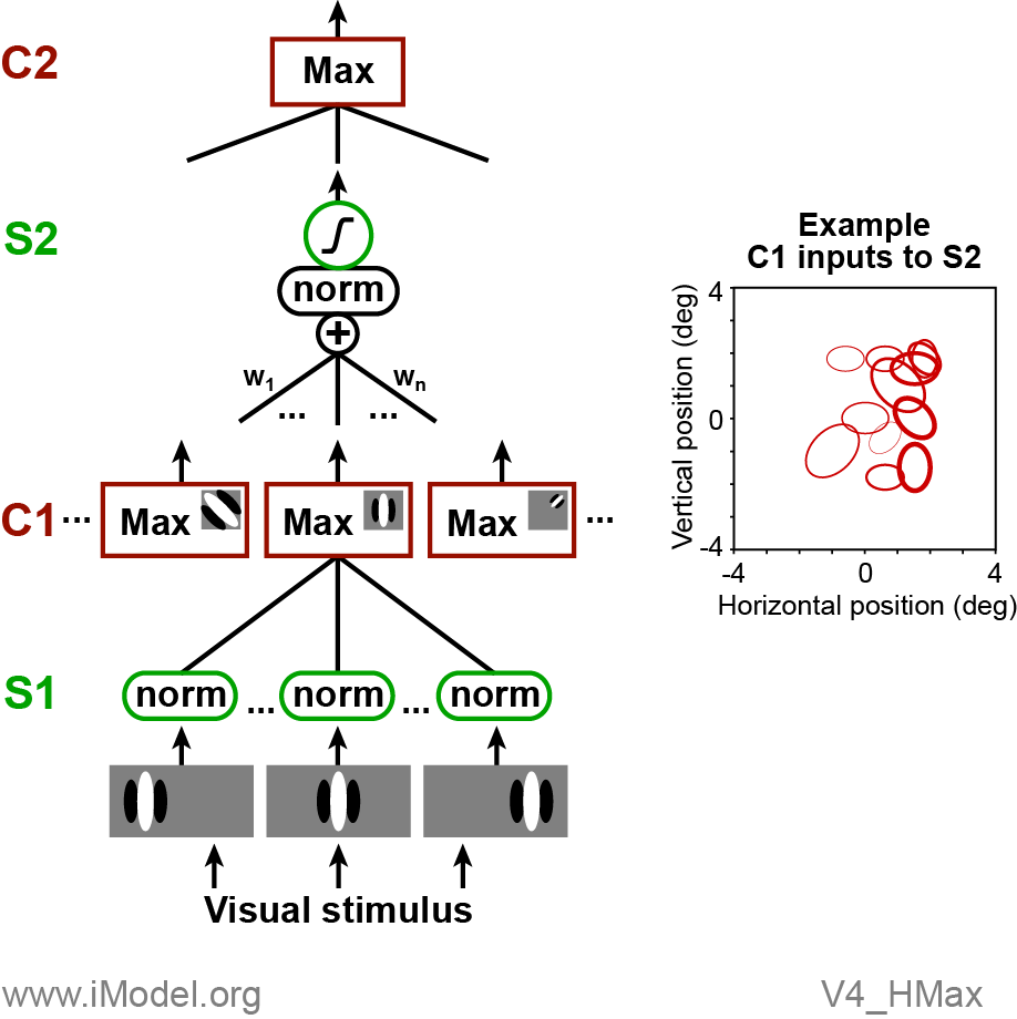
The C1 units in the second-layer compute a Max() function over their input array, which consists of many S1 units that share the same orientation but vary in local position (within a square region centered on the location of the C1 unit), spatial phase and size. By taking a Max() over position and phase, the C1 units become phase and position invariant while preserving orientation tuning. In this way, they are roughly analogous to V1 complex cells. Each C1 unit (red rectangles in C1 layer) is defined by tuning for three attributes: (1) location in the visual field, (2) orientation preference and (3) spatial scale.
The S2 units take a weighted sum of a subset of the available C1 units. The sum is normalized and passed through a sigmoidal nonlinearity. In the Cadieu model fits to V4 neurons, an S2 unit would have non-zero weights for between 2 and 25 C1 units. By selecting specific C1 units, the S2 unit can in theory achieve tuning for a particular pattern of oriented features across space. A graphical depiction of an example S2 "shape template" is shown (right side of figure) where one ellipse is plotted for each of the C1 inputs. The orientation, size and location of the ellipse indicate the orientation, scale and location of the C1 inputs. The thickness and color of the line indicate the amplitude and sign (red is positive, blue is negative) of the C1-to-S2 weights.
The final C2 unit takes a Max() function over 9 inputs, which consist of a 3 x 3 grid of S2 units, each of which has identically the same set of C1 weights. The final C2 unit is essentially designed to improve translation invariance by taking a Max over identically tuned, but spatially offset, inputs.